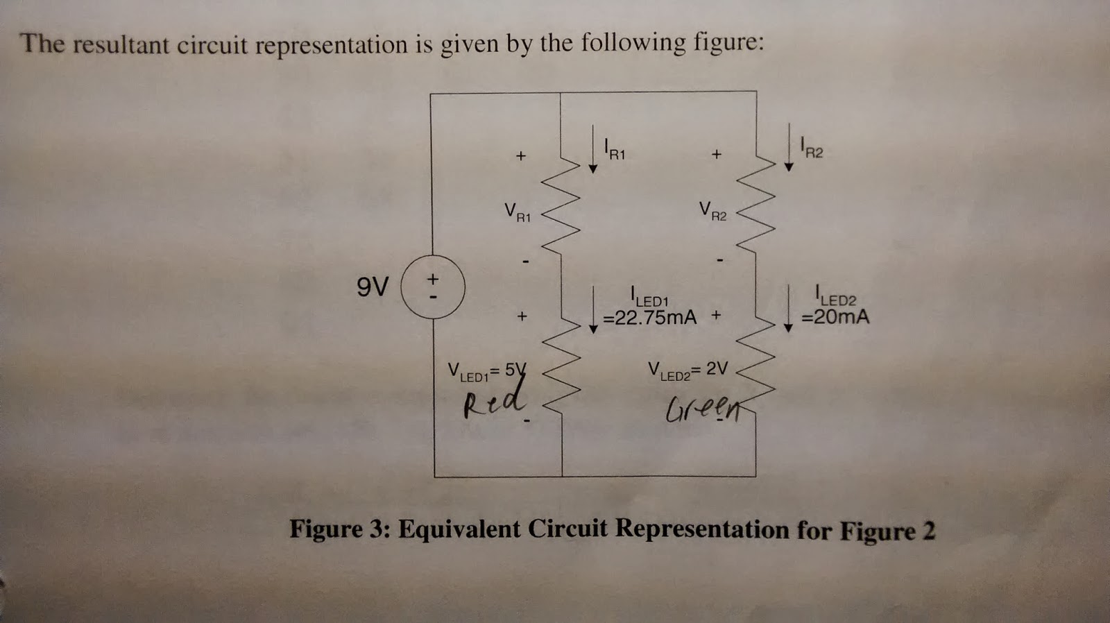
Summary: In a parallel circuit, different branches share the same power supply; however, the components in each branch may only work under the supply voltage. Resistors are used to drop the voltage in a branch in order to create proper voltage for the load components.
Schemetic
Designed values. Because resistors are only availabe in certain values, the actual R1 is 220 ohms, and R2 is 470 ohms.
Final setup.
Connect meters to different branches to collect readings.
Data
a. The operating time for 0.2A-hr.
b. The percent error between the theoretical value and the actual value is
-19.21% . The causes include:
- the actual LED working voltage and amperage may not be the same as labled.
- The LEDs may not follow Ohm's Law perfectly.
- The meters affected the circuit and slightly affected the reading.
c. Calculate the power efficiency.
d. If the vattery is 6V, efficiency will go up because the LEDs take a larger portion of the voltage while the current stay the same. For the same reason, the lower voltage, the higher efficency. The lowest voltage is 5V in this case.
(5*22.75+2*20)/(5*(22.75+20))=71.9%
Bouns
Notes: The actual resistors used are much larger than the designed values; therefore, the readings are also very different from the designed values. The LEDs probably do not follow Ohm's Law in its entire working voltage range. Overall the biasing resistors allow both LEDs work in this circuit.


No comments:
Post a Comment